Analog Lab Report Week 13

1.

Wow. Dominic’s reactive lamp project is so cool! I’ve also always wanted to build something like this! For my project next semester I will build something responsive to the environment as well! That’s a must. I will do it for sure.

Jordana’s project is also really fun! I’ve always believed that motion capture would require something really sophiscated hardware to achieve, but she only used three acceleration cencers. Now there’s more cencers I can play with.

Hank’s project seems complicated but seems to have huge utility. He uses a motor, making me ponder if I can use a motor to do anything in my future project.

2.

https://create.arduino.cc/projecthub/Jalal_Mansoori/simplest-way-for-voice-recognition-project-using-c-toarduino-105138

This is a voice recognition module built using C# and Arduino. I’ve always thought of voice recognition as something being so complicated that might involve something like machine learning. So far I don’t quite understand how it works since I don’t get the code, but I will revisit it in the future.

This is a mini gaming console built using Arduino. It’s small but it looks so nice and fine. I’m kind of excited for the potential of what Arduino can do.

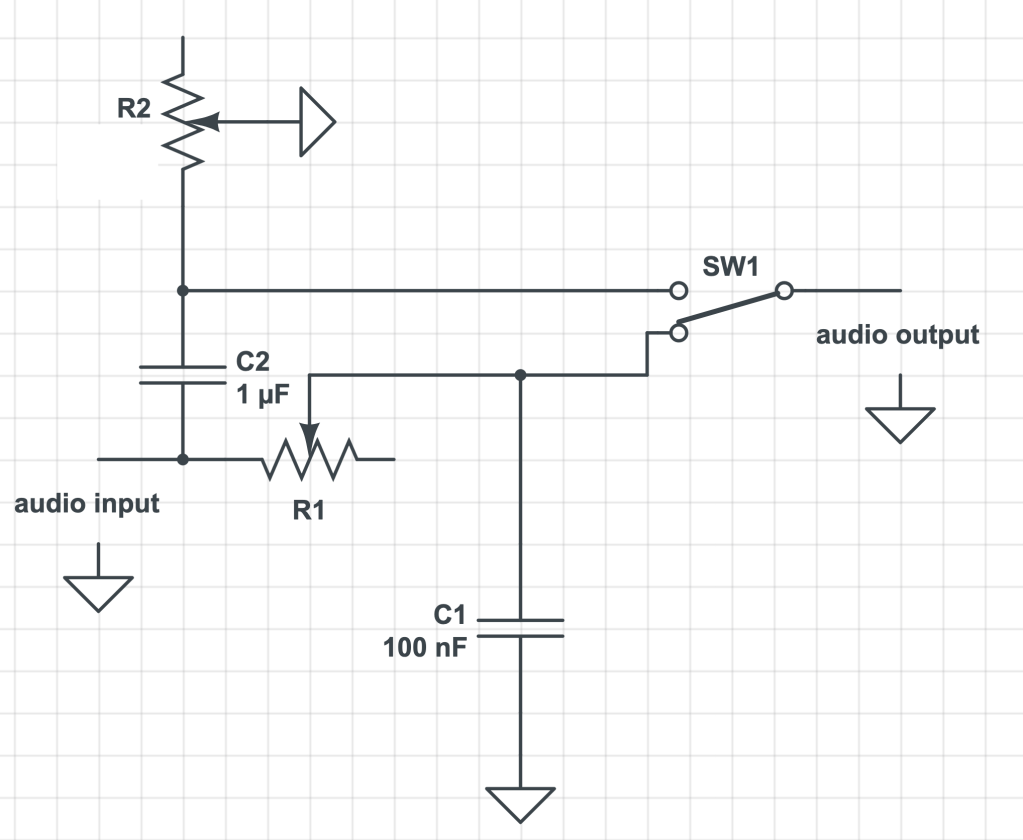
3. In digital electronics terms, a switch or button is a digital input, an LED is a digital output, and a potentiometer is an analog input.

4. I have taken Intro to Computer Programming in the first semester of Freshman learning Python, and I’m taking Intro to Computer Science this semester using Java. I will continue to take Data Structure this summer using Python. I’m planning to double major in Music Tech and CS. I’ve not done any project yet but I’m excited for the digital electronics class!

Analog Lab Report Week 12


https://www.multisim.com/content/RH9q3x5ywRDWxfBnq2yLM6/week-12/open/

The resistance of R1 is 2/1.1/0.00001 = 181818 ohms

I found another example on http://www.555-timer-circuits.com/laser-ray-sound.html in which the curcuit demonstrates a weird “Laser Ray” sound and flashes a white LED at approx 5Hz. It should be an astable multivibrator since it needs to switch between the on and off states.

Analog Lab Report Week 11

Some pedals like Blackout Effectors have so many different knobs. The variety of combinations allow users to use it in so many creative way, but it could potentially make it complicated to use. Most pedals only have two or three knobs, focosing on several effects, making themsevles easy to use.

I would say large companies are making pedals for more general uses. Users are the general public. The effects are just more standadized. However, smaller companies are making pedals that are more stylish and special. It’s just interesting to check out these creative pedals.

The Electro-Harmonix 8-Step Program Analog Expression Sequencer Guitar Effects Pedal has a step sequencer that without a gradual movement. You basically have to “program” certain steps, and these steps can be repeated in a loop.

https://www.samash.com/other-effect-pedals/electro-harmonix-8-step-program-analog-expression-sequencer-guitar-effects-pedal-e8stepprg

SP5T means a single-pole 5-throw switch.

A Momentary switch remains in its “on” (or “off”) state only as long as it is being compressed. It can be used for products that are dangerous to be left on like hair driers. A latching switch needs to be pressed once for ON and again for OFF, for example a light switch.

Analog Lab Report Week 8

1) With the oscillator we’re studying the comparator outputs a ___square____ wave and the integrator outputs a ___triangle____ wave.

2) With an integrator, if Vin is positive the output voltage ramps __down____ (up/down). If Vin is negative the output voltage ramps __up_____ (up/down).

Screen Shot 2020-03-23 at 10.22.06 AM

3) With a comparator, if the op amp’s + input is connected to a greater voltage that that connected to it’s – input, the op amp’s output will be about _positive__ (positive/negative) 9v DC.  If the op amp’s + input is connected to a lower voltage that that connected to it’s – input, the op amp’s output will be about __negative___ (positive/negative) 9v DC.

4) There’s a formula for how fast the integrator ramps up or down:

change in volts per second at Vout = -Vin / RC

So the bigger the resistance R you use the ___slower_______ (faster/slower) the ramp gets, and the bigger the capacitor gets the __faster________ (faster/slower) the ramp gets.

5) The circuit at the end of this video is a monophonic synthesizer – it can only output one tone at a time. What do you think would have to do to make a polyphonic synthesizer that could play 2 notes at the same time? 3 notes? 4 notes? 100 notes?

Using multiple oscilators at the same time? 

Analog Lab Report 6

2a) 

The capacitor for 100k ohms potentiameter:

1 / (2 * 3.14159 * 100000 ohms * 16 Hz) ≈ 10 ^ -7 F

2b)

2c) 

The capacitor for 10k ohms potentiameter:

1 / (2 * 3.14159 * 10000 ohms * 16 Hz) ≈ 10 ^ -6 F

2d)

3)

4) 

Putting multiple -6 dB filters in series?

5)

  1. I want to make a filter that is responsive to the environment. What I’m thinking right now is doing a filter that varies based on the brightness a photocell perceives. It could be used in places like a disco room where lighting changes. 
  2. Of course, brightness could be just one of the factors that change the output. I want to have multiple environmental factors that affect the audio output together, but I’m not sure what other factors I can take advantage of. I want to make use of all the effects that we learn in this semester and assign them to each factor. 
  3. Distortion? I’m not sure how distortion works. I saw some projects doing distortion in some previous years. I think it would be interesting if I can incorporate distortion into my own project.

Troubleshooting

Putting a switch right after the audio input will accidentally parallel the two resistors. Instead, we should put the switch right before the audio output. 

Analog Lab Report 3

The View Mode will show what different channels look like. If you want to see both of the channels, use “dual” mode. The vertical Position knobs let you shift your waves up and down. You should center the waves in the middle. The Volts per div knob lets you expand or shrink your wave vertically, but you should turn smaller Volts Per Div knob all the way to the right until it clicks. The input mode switch lets you choose either the ground mode or the DC mode. Never use the AC mode. Set Trigger Source to Channel 1. The Trigger Mode to either Auto or TV-V.  Time Per Div knobs let you decide how wide horizontally a wavelength is. 

The X-axis shows time. The “time per div” demonstrates what the wave looks like, in one div,  when it travels over a specific amount of time. The Y-axis shows the volts. The “volts per div” demonstrates how many volts are shown in one div. 

The trigger mode (TV-V)  allows you to set the wave still and make it easier to observe. The Trigger Source allows you to take one of the sources as a reference source and it syncronizes the other source with the reference source. 

The wave of the second source matches up with the source one when it reaches its maximum amplitude. It becomes a flat line when it reaches its minimum amplitude. The range is 0% – 100% of the input wave. 

Analog Lab Report 3

Part 1a

  1. Open the window. 
  2. Get the sponge wet. 
  3. Turn on the soldering iron. 
  4. If it reaches the temperature, when the iron touches the wet sponge, it should make some sounds. 
  5. In order to clean the tip of soldering iron, rub it on the sponge. 

Part 1b

  1. Switch the soldering iron off. 
  2. Clean the tip of the soldering iron by rubbing it on the sponge.
  3. Close the window before it gets too cold. 

Part 2a

You need to check if the two wires are in the right place. It is different for measuring the voltage from the current. 

Part 2b

Measured Voltage: 8.31V

Power = (V/R) * V = 8.31 ^ 2 / R < 0.25 W

8.31 ^ 2 / 0.25 < R

R > 276.22 Ω

Therefore, the smallest should be 330 Ω. But for safety, I will go for the next smallest one, which is 470 Ω.

The measured current is 0.018A. The power should be 8.31V * 0.018A = 0.15W, which is well below the upper limit. 

Part 2c

I2 = 8.31V / 1000 Ω = 0.00831A

I3 = 8.31V / 1000 Ω = 0.00831A

I4 = 8.31V / 2200 Ω = 0.00378A

I5 = 8.31V / 3300 Ω = 0.00252A

I1 = I6 = 0.00831A + 0.00831A + 0.00378A + 0.00252A = 0.02292A

Measured value:
I1 = I6 = 0.019A
I2 = 0.008A
I3 = 0.008A
I4 = 0.004A
I5 = 0.002A

Design a site like this with WordPress.com
Get started