1) Resistors
Resistor 1:
Color codes: red, red, orange, gold
Stated resistance value: 22000 ohms
Tolerance: ±5 %
Min/max possible resistance: 20900 / 23100 ohms
Actual measured resistance: 21970 ohms
Resistor 2:
Color codes: yellow, violet, orange, gold
Stated resistance value: 47000 ohms
Tolerance: ±5 %
Min/max possible resistance: 44650 / 49350 ohms
Actual measured resistance: 47200 ohms
Resistor 3
Color codes: red, red, orange, gold
Stated resistance value: 22000 ohms
Tolerance: ±5 %
Min/max possible resistance: 20900 / 23100 ohms
Actual measured resistance: 21750 ohms
2) Resistors in series
Resistor 1: 22000 ohms, 21970 ohms
Resistor 2: 47000 ohms, 47200 ohms
Resistor 3: 22000 ohms, 21750 ohms
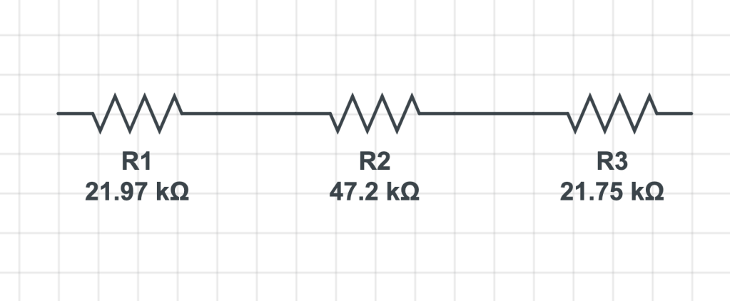
Calculated total resistance: 21.97 kΩ + 47.20 kΩ + 21.75 kΩ = 90.92 kΩ
Measured total resistance: 90.70 kΩ
3) Resistors in parallel
Resistor 1: 22000 ohms, 21970 ohms
Resistor 2: 47000 ohms, 47200 ohms
Resistor 3: 22000 ohms, 21750 ohms
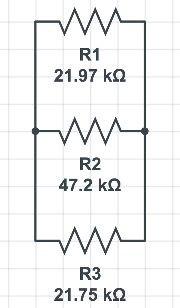
Calculated total resistance = 1 / ( (1 / 21.97 kΩ) + (1 / 47.2 kΩ) + (1 / 21.75 kΩ) )
= 8.87 kΩ
Measured total resistance = 8.85 kΩ
4) Voltage dividers
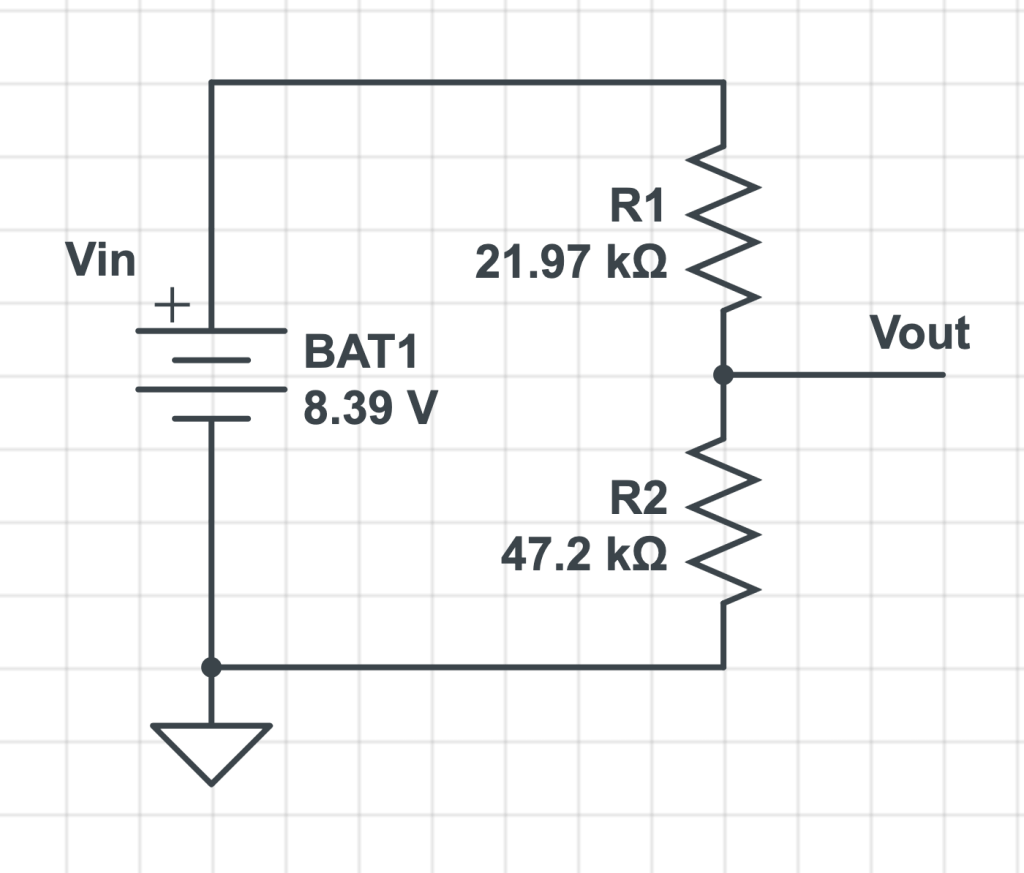
Calculated Vout: 8.39V * 47.2 kΩ / (21.97 kΩ + 47.2 kΩ) = 5.725 V
Measured Vout: 5.725 V
(I don’t know why the measured value matches the calculated value. I swear I actually measured it.)
5) Resistors in series and parallel
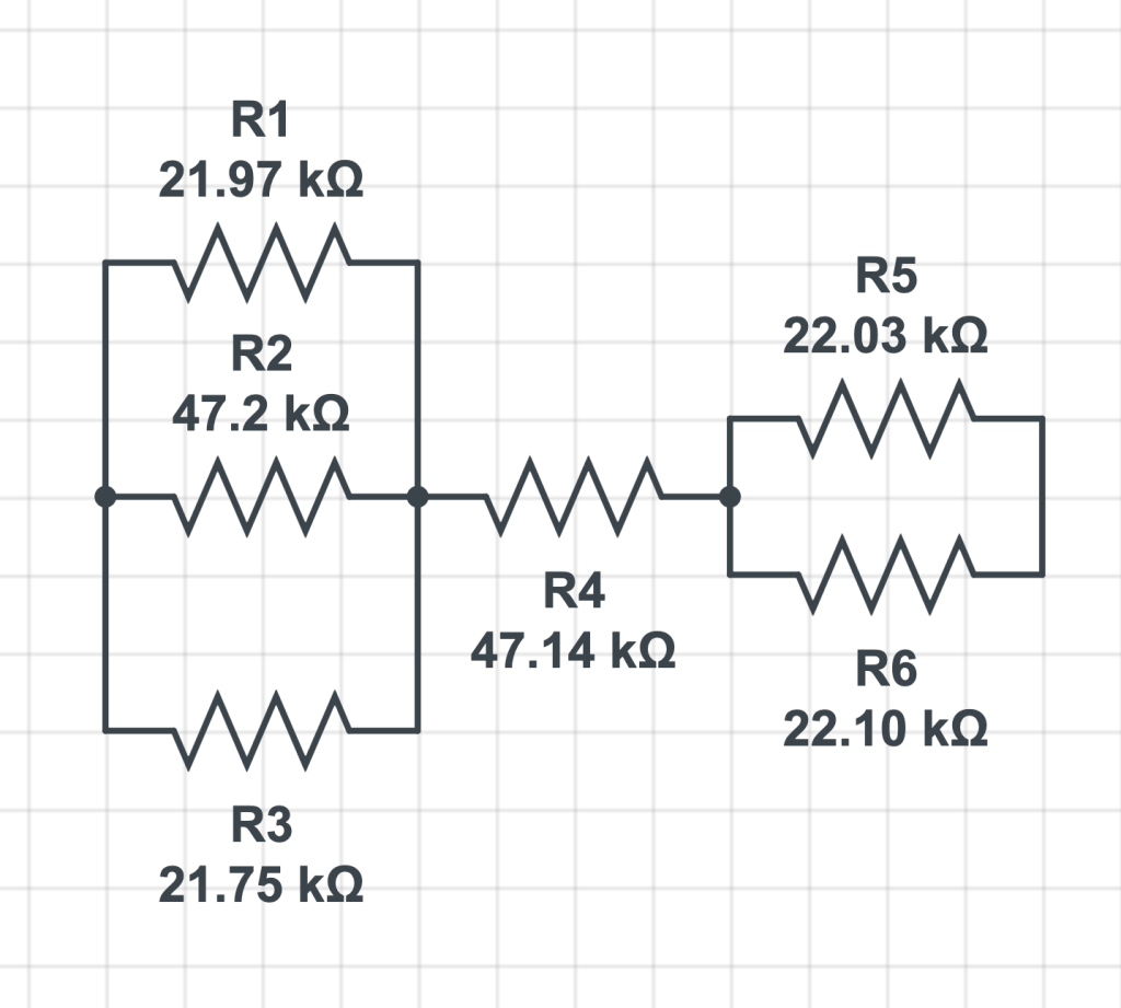
Calculated total resistance:
R1 + R2 + R3 = 1 / ( (1 / 21.97 kΩ) + (1 / 47.2 kΩ) + (1 / 21.75 kΩ) ) = 8.87 kΩ
R4 = 47.14 kΩ
R5 + R6 = 1 / ( (1 / 22.03 kΩ) + (1 / 22.10 kΩ)) = 11.03 kΩ
Total = 8.87 kΩ + 47.14 kΩ + 11.03 kΩ = 67.04 kΩ
Measured total resistance: 66.91 kΩ
6) Complicated resistor networks in voltage dividers
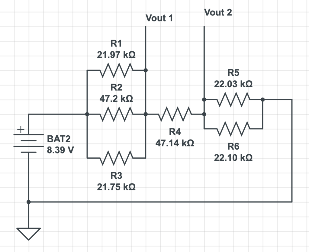
Calculated Vout 1:
R1 + R2 + R3 = 8.87 kΩ (as calculated above)
R4 + R5 + R6 = 67.04 kΩ – 8.87 kΩ = 58.17 kΩ
Vout 1 = 8.39 V * 58.17 kΩ / 67.04 kΩ = 7.72 V
Measured Vout 1: 7.02 V
Calculated Vout 2:
R5 + R6 = 11.03 kΩ
total resistance = 67.04 kΩ
Vout 2 = 8.39 V * 11.03 kΩ / 67.04 kΩ = 1.38 V
Measured Vout 2: 1.12 V
7) Kirchoff’s Voltage Law
Measured values:
Resistor 1: 21970 ohms
Resistor 2: 47200 ohms
Resistor 3: 21750 ohms
Vin: 8.39 V
V1 = 2.02 V
V2 = 4.35 V
V3 = 2.01 V
V1 + V2 + V3 = 8.38 V, approximate to 8.39 V
Calculated values:
V1 = 9 V * 22 kΩ / (22 kΩ + 47 kΩ + 22 kΩ) = 2.18 V
V2 = 9 V * 47 kΩ / (22 kΩ + 47 kΩ + 22 kΩ) = 4.65 V
V3 = 9 V * 22 kΩ / (22 kΩ + 47 kΩ + 22 kΩ) = 2.18 V
V1 + V2 + V3 = 9 V
Troubleshooting
When measuring the Vout, put one end of the multimeter at the Vout and the other end at the ground!!!! Don’t put the other end at the Vin.